Tutorial: Ultrasonic Sensor (Mode 1: GPIO Method)
Introduction
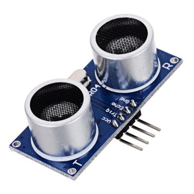
In this tutorial we will be using the latest 2021 version of the popular HC-SR04 Ultrasonic sensor and connect it to the Arduino Nano using a simple IDE script. It is important to note that this 2021 version of the sensor is different in notable ways compared to the old versions that have flooded the market. The first difference is that the accepted input voltage now ranges from 2.8V to 5.5V. This is convenient if you want to power the sensor with a microcontroller as it will work with either a 3.3V microcontroller or a 5V microcontroller. In this tutorial we will be using the common 5V Arduino Nano, but use the 3.3V pin to power the sensor as this will reduce the current draw. Speaking of which, this sensor is pretty great when one’s power budget is running low as the current drawn can be as low as 2mA while active.
The second important difference is the way the sensor can communicate with the microcontroller. The old version can only use the general purpose input/output (GPIO) pins, whereas this latest 2021 version can connect in four different ways. Namely:
Mode 1: GPIO
Mode 2: I2C
Mode 3: 1-Wire
Mode 4: UART
In this tutorial we will be focusing on the common method of Mode 1: GPIO. The other three methods require the user to solder a jumper across a couple of connections on the back of the sensor itself in order to select the desired mode. We will not go into this detail here as these other three methods will be covered in different tutorials.
Required Hardware
- 1 X Ultrasonic sensor (2021 version)
- 1 X Arduino Nano
- 1 X Standard breadboard
- A few jumper wires
Setting up the hardware
Using the GPIO pins (Mode 1) to communicate with the Nano is pretty straight forward. Make the following four connections, as shown in the picture below:
- VCC pin on the sensor to the 3.3V pin on the Nano.
- GND pin on the sensor to GND pin on the Nano.
- Trig pin on the sensor to D7 pin on the Nano.
- Echo pin on the sensor to D6 pin on the Nano.
 Connecting the ultrasonic sensor to the Nano.
You might be wondering why we are using the 3.3V pin to power the sensor? The 2021 version allows as an input voltage a minimum of 2.8V and a maximum of 5.5V. From our experimentation we found that the current draw vs. VCC voltage is as follows: VCC [V] Current draw [mA] 3.0 2.0 3.3 2.3 5.0 3.6 Table 1: Current consumption with different input voltages. We can see that the lowest current consumption is when the sensor is connected to 3V. However, the onboard voltage regulator on the Nano outputs 3.3V, not 3.0V. Therefore we pick that voltage as it is easily available. Setting up the software It is assumed that the user has already installed the IDE software and is familiar how to select the correct settings in order to upload scripts to the Nano. If the user is not familiar with these steps, see our tutorial on first time using the Nano microcontroller. Simply copy the following script into the IDE software.
// Project title: "Tutorial: Ultrasonic Sensor (Mode 1: GPIO Method)"
// Date of last edit: Dec 4 2021, PTSolns
// For bugs or questions please send us an email at contact@PTSolns.com
// Overview: This is the script for interfacing the ultrasonic sensor (version 2021) in Mode 1 (GPIO) // Tutorial: https://ptsolns.com/ultrasonic-sensor-tutorial-GPIO/
// Set trigger and echo pins
const int trig_pin = 7;
const int echo_pin = 6;
void setup() { Serial.begin(9600); // Starting Serial Terminal }
void loop() { long duration, inches, cm; pinMode(trig_pin, OUTPUT);
digitalWrite(trig_pin, LOW);
delayMicroseconds(2);
digitalWrite(trig_pin, HIGH); delayMicroseconds(10); // The HC-SR04 ultrasonic sensor requires only a 10us trigger pulse.
This actives the module to send 8 pulses at 40kHz.
digitalWrite(trig_pin, LOW);
pinMode(echo_pin, INPUT); // Listen to the echo pin.
duration = pulseIn(echo_pin, HIGH); // The duration is the time between the sending of the 8 pulses and the return of the 8 pulses.
// Convert duration to distance (inches and cm) inches = duration / 74.0 / 2.0; cm = duration / 29.0 / 2.0;
// Print results to monitor Serial.print(inches);
Serial.print("in, ");
Serial.print(cm);
Serial.print("cm");
Serial.println();
delay(100); }
Results and conclusion
Upon opening the serial monitor after successful upload of the script we can see a steady stream of values. The output is present in both inches and cm. Play around with the sensor by placing different objects at various distances to the sensor. Note that some objects provide better results than others. Fabrics, carpets and other objects/materials that tend to absorb the 40kHz ultrasonic signal give poorer results in terms of determining the correct distance. Also keep in mind that the sensor has a spread of about 15 degree in a conical shape. This might provide incorrect reading when multiple objects are in front of the sensor and various distances along the conical shape. With this simple tutorial you can advance to more complicated projects. You are not required to use the 3.3V pin on the Nano, nor do you even have to use the Nano. The next step one could take is add an LCD screen and print out the results there, instead of on the serial monitor. More complicated projects can be done by adding an additional ultrasonic sensor and getting more accurate results. Finally note that there are three other methods to interface the sensor to the microcontroller. Here we examined only the GPIO method, but the other three methods might be of interest to the reader. Links are as follows: Tutorial: Ultrasonic Sensor (Mode 2: I2C Method) … Coming Soon Tutorial: Ultrasonic Sensor (Mode 3: 1-Wire Method) … Coming Soon Tutorial: Ultrasonic Sensor (Mode 4: UART Method) … Coming Soon FacebookLinkedIn